Stereo Pi - An Experiment in DIY Stereo System - Part 2
Greetings from the Nut Hutch. Thailand is in the middle of their Songkran celebrations and it is very hot outside. So I thought today would be a good day to take a break from the heat and celebrations to finish discussing my Stereo Pi project. In my previous post, link, I listed the parts I used in this project. Now it is time to put them all together to make a working system.
Speakers
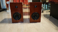 Because they were the first component that I had all the parts for, the first thing I assembled were the speakers. As stated before, the speakers I used were originally designed for use with a car stereo. In order to use them properly with a home stereo, some special care had to be taken in their construction. The first has to do with the size of the speaker box. If the box is too large, the low frequencies produced by the speakers will not be heard. On the flip side, if the box is too small, the lows produced will be muddled. I decided to use a very unscientific method to figure out the size of box that I needed. I measured the internal volume of doors from six different cars, and calculated their average volume. This average is what I used for the internal volume of the speaker boxes.
 I personally do not have the knowledge or skill to make these boxes myself. So I asked a friend of mine who does have the required skill set what materials I should use and if he could build them for me. After some discussion, we decided to go with some cabinet grade 1/2 inch plywood. All of the measurements I took in determining the speaker cabinet's required volume were internal measurements. This left me with another math problem. After taking off my shoes so I could count to twenty, I determined the external dimensions needed were: 17" (43cm)H X 9 1/4" (14cm)W X 12" (30cm)D. While this seems rather big, it does come with some flexibility. I can always remove the back of the speaker and add some foam padding if I need to reduce the internal volume. Overall, I am pleased with the sound they are giving right now, but I know the tinkerer in me will want to play around with the internal volume sometime in the future.
 Another problem with using car speakers with a home stereo is their magnets. You see, most speakers designed for home stereo use are magnetically shielded. This shielding used to be especially important in the days of the CRT television and computer monitor. If you placed a speaker magnet close to tube television or CRT monitor, it would distort the color. Keep the magnet next to it long enough, and you will permanently damage the monitor/ television. While this not a real concern in today's world of LED/ LCD monitors and televisions, adding some sort of magnetic shielding gave me some piece of mind. Since all that is needed to this is some sort of ferrous metal around the magnet, I went on a search to find something that would work. After going to some of the local home improvement stores, I ended up in a combined automotive exhaust and machine shop. There I was able to have the cap you see manufactured, for a 12 pack of beer, from scrap metal they had laying around. These caps were then attached to the speaker's magnet using 3M tape. This reduced their magnetic emissions to a point were I could set them next to a CRT monitor all day without affecting the picture quality.
Stereo System
Once I had the speakers built and all the parts gathered, it was time to build the system. I decided that before I have the enclosure built, I needed to test all the components to make sure that they are running properly. This type of testing is a good idea no matter what type of system you are assembling. This allows you to replace any component that doesn't work before you begin assembly. So I did a quick and dirty test by assembling the system on my work table. I was quite pleased to see that everything worked properly together. This test did have a downside though. I was totally impressed with the sound of the speakers. This left me impatient to finish the project! Once this bench test was complete, I set about determining how big a chassis I wanted to have built for the system.
The chassis that I wanted needed to meet two requirements. The power supply for the system needed to be internal and I wanted it to look similar to an old television. To do this, I laid out the parts on a black piece of plastic "cardboard". This allowed me to not only visualize how everything would fit inside the case, but also to determine the size of case that I needed. Another advantage of doing a layout in this manner, it allowed me to experiment with the placement of the hardware in a non-permanent manner. This way, when it came to actually building the chassis, I knew where everything was placed and could drill the appropriate holes one time. Unfortunately, I am unable to share a picture of my layout here because forgot to take a picture of it before I recycled the board into another project.
Internal Layout
 As part of this layout, I needed to figure out a way of running power to the Raspberry Pi and my USB hub. Since I only wanted one power lead attached to the system, this meant that some sort of internal distribution box was needed. After getting a "sanity check" from a friend of mine who is an electrician, I decided to go with a surge protector wired to a fused switch. This combination gives the system a double layer of protection. The surge protector will insulate the system from minor power spikes, and the fused switch will give it some protection from major power spikes. The picture on the left shows the end result. The power brick in the picture provides power to the Raspberry Pi and amplifier setup. The other outlet is for the USB hub.
 Next I had to figure out the placement of the USB hub. I chose the USB hub I did because of the layout of its ports. They are situated in such away that it allows me to have two ports outside and two ports inside of the chassis. This makes it easy to plug in my USB WiFi dongle and remote control. As shown in the picture on the right, I placed the internal speaker connections above the USB hub. These connections run between the amplifier and some standard binding posts. I found that the best place to put the USB Hub and the speaker posts were on the opposite side from the power input. This placement allowed me to add a large cooling fan (exhaust) in between them. This fan allows for an even airflow across all the components.
 Now that I had the power and USB hub locations sorted, I could place the rest of the components into my drawing. The picture on the right shows how everything fit together after the chassis was built and finished. From left to right, we have the power brick, surge protector, the external laptop hard drive, exhaust fan (back) and LCD Panel (front), Raspberry Pi/ Amplifier, and the USB hub. The Raspberry Pi and the LCD screen are attached to the chassis using standard 2.5mm diameter brass motherboard stand-offs and screws. The hard drive and surge protector are mounted using the 3M Command Picture Hanging Strips, link. These strips are basically industrial strength Velcro. Not only do these strips provide a stable mounting for these items, but they allow me to easily remove these components if I need to. The power brick is held in using 3M Bundling Straps, link, attached to the side of the chassis using some small screws. These provide a strong and stable mounting for the power brick. Since they are also industrial strength Velcro, the power brick is easily removed in case it needs replacement. The cables connecting the various components are routed using some cable mounting clips. Overall, I think the interior of the chassis turned out quite well. There is enough airflow through the case, where even in the heat of summer, the components stay cool.
External Layout - Front
 The front of the box turned out, in my mind quite nice. From left to right in the picture, we have the LCD screen, intake grill for airflow, the power button, and the volume control. While the goal was to have a a retro style television look, I was limited to the placement of the power switch and the volume control by the length of their wires. Yes, I could have replaced them with longer wires, it was just not something I wanted to do at the time. Overall, I personally like the look that I ended up with. I am still thinking about something I can put in the large space next to the LCD screen however. Just to give it some sort of pseudo-branding.
External Layout - Rear
 The rear of the box is quite simple. From left to right in the picture, we have the USB hub, speaker connectors, exhaust fan, and the power lead connector. The exhaust fan is attached to the rear using standard case fan screws. Despite the large case fan, I still have room to to add more connections in the future. For example, I may want to add some external RCA jacks or even an RJ-45 ethernet port. These can easily be placed above the external speaker connectors.
Once I had determined the layout of all of my components, I talked to my carpenter friend again. As with the speakers, we decided to build the chassis using cabinet grade 1/2 inch plywood. We decided on plywood because it has a far less chance of warping and cracking than real wood. Because I live in a country with high humidity, I felt it was the best material to use. The decision was also easy to make because he had some leftover plywood from another project and was willing to let it go, and do the manufacturing, for a case of beer. The exterior of the chassis, as well as the exterior of the speakers, were finished using a Berger Teak stain and polyurethane combo. The interior of the chassis was painted using some flat black spray paint.
Software
As stated in my previous post, I decided to use OSMC as the software for my project. It is very easy to install onto a microSD card using Etcher. There was very little configuration required during install. OSMC automatically sets itself up to mount any attached storage device automatically on boot. It was really nice not having to edit the fstab to accomplish this. After install, I was presented with the very familiar Kodi interface. Since it uses Kodi, it was quite easy to configure. After five minutes spent configuring my remote and making sure that the sound card was the default audio device, I was ready to scan in my media. Once this was scan was completed, I was up and running.

I am very pleased with how this project turned out. Not only was it fun to find the parts and put them together, it was a learning experience for me as well. This was my first time working with a Raspberry Pi. It was very interesting to see the differences between it and a full sized computer. Not only did I learn about the Raspberry Pi, but I learned about electricity and just what it takes to make a computer case. It was an eye opening experience for me. Ultimately, I could not have done this project without the knowledge and help from some great individuals. "Aussie" Ron Dromer for his help in making both the speaker boxes and the stereo chassis itself. John Kolak for the donation of the Kicker speakers. Soren Sorensen for educating me and conducting "sanity checks" on my electrical work. Finally the wonderful group of people at over at Podnutz, link. Without them sharing their knowledge of the Raspberry Pi and other mini-computers, I would not have even thought about building my own system. Thank you all for sharing your knowledge and support. I truly do appreciate it!
I hope you enjoyed this look into my Stereo Pi project. I had quite a bit of fun not only doing the project but sharing it with you. I am still giving some thought to what my next blog post will be about. I have several ideas that I am looking at. Thank you all for reading.
Cheers!
Speakers


Stereo System
Once I had the speakers built and all the parts gathered, it was time to build the system. I decided that before I have the enclosure built, I needed to test all the components to make sure that they are running properly.

The chassis that I wanted needed to meet two requirements. The power supply for the system needed to be internal and I wanted it to look similar to an old television. To do this, I laid out the parts on a black piece of plastic "cardboard". This allowed me to not only visualize how everything would fit inside the case, but also to determine the size of case that I needed. Another advantage of doing a layout in this manner, it allowed me to experiment with the placement of the hardware in a non-permanent manner. This way, when it came to actually building the chassis, I knew where everything was placed and could drill the appropriate holes one time. Unfortunately, I am unable to share a picture of my layout here because forgot to take a picture of it before I recycled the board into another project.
Internal Layout


External Layout - Front

External Layout - Rear

Once I had determined the layout of all of my components, I talked to my carpenter friend again. As with the speakers, we decided to build the chassis using cabinet grade 1/2 inch plywood. We decided on plywood because it has a far less chance of warping and cracking than real wood. Because I live in a country with high humidity, I felt it was the best material to use. The decision was also easy to make because he had some leftover plywood from another project and was willing to let it go, and do the manufacturing, for a case of beer. The exterior of the chassis, as well as the exterior of the speakers, were finished using a Berger Teak stain and polyurethane combo. The interior of the chassis was painted using some flat black spray paint.
Software
As stated in my previous post, I decided to use OSMC as the software for my project. It is very easy to install onto a microSD card using Etcher. There was very little configuration required during install. OSMC automatically sets itself up to mount any attached storage device automatically on boot. It was really nice not having to edit the fstab to accomplish this. After install, I was presented with the very familiar Kodi interface. Since it uses Kodi, it was quite easy to configure. After five minutes spent configuring my remote and making sure that the sound card was the default audio device, I was ready to scan in my media. Once this was scan was completed, I was up and running.

I am very pleased with how this project turned out. Not only was it fun to find the parts and put them together, it was a learning experience for me as well. This was my first time working with a Raspberry Pi. It was very interesting to see the differences between it and a full sized computer. Not only did I learn about the Raspberry Pi, but I learned about electricity and just what it takes to make a computer case. It was an eye opening experience for me. Ultimately, I could not have done this project without the knowledge and help from some great individuals. "Aussie" Ron Dromer for his help in making both the speaker boxes and the stereo chassis itself. John Kolak for the donation of the Kicker speakers. Soren Sorensen for educating me and conducting "sanity checks" on my electrical work. Finally the wonderful group of people at over at Podnutz, link. Without them sharing their knowledge of the Raspberry Pi and other mini-computers, I would not have even thought about building my own system. Thank you all for sharing your knowledge and support. I truly do appreciate it!
I hope you enjoyed this look into my Stereo Pi project. I had quite a bit of fun not only doing the project but sharing it with you. I am still giving some thought to what my next blog post will be about. I have several ideas that I am looking at. Thank you all for reading.
Cheers!


Great to see a collision repair shop in Hollywood that uses modern tools and experienced technicians. Your dedication to restoring vehicles safely and efficiently is clearly reflected on the site. collision repair shop in Hollywood
ReplyDelete